Specification of Tubing Hanger
| Bottom Flange Size | Working Pressure | Top Flange Size | Working Pressure | Outlet |
| in | psi | in | psi | |
| 7 1/16 | 3000 | 11 | 2000 | 2 LP" |
| 7 1/16 | 3000 | 11 | 3000 | 2 LP" |
| 7 1/16 | 3000 | 11 | 3000 | 2 1/16 LP" |
| 7 1/16 | 3000 | 13 5/8 | 3000 | 2 1/16 LP" |
| 7 1/16 | 5000 | 9 | 3000 | 2 1/16 LP" |
| 7 1/16 | 5000 | 11 | 3000 | 2 1/16 LP" |
| 7 1/16 | 5000 | 11 | 5000 | 2 1/16 LP" |
| 7 1/16 | 5000 | 13 5/8 | 3000 | 2 1/16 LP" |
| 7 1/16 | 10000 | 11 | 5000 | 1 13/16 LP" |
| 7 1/16 | 10000 | 11 | 5000 | 2 1/16 LP" |
| 7 1/16 | 10000 | 11 | 10000 | 1 13/16 LP" |
| 7 1/16 | 10000 | 11 | 1000 | 2 1/16 LP" |
| 11 | 3000 | 13 5/8 | 3000 | 2 1/16 LP" |
| 11 | 5000 | 11 | 3000 | 2 1/16 LP" |
| 11 | 5000 | 11 | 5000 | 2 1/16 LP" |
| 11 | 5000 | 13 5/8 | 5000 | 2 1/16 LP" |
| 11 | 10000 | 11 | 5000 | 1 13/16 LP" |
| 11 | 10000 | 11 | 10000 | 2 1/16 LP" |
| 11 | 10000 | 13 5/8 | 5000 | 1 13/16 LP" |
| 11 | 10000 | 13 5/8 | 5000 | 2 1/16 LP" |
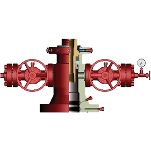
Tubing hanger is designed with 45° shoulder and straight seat, with good load bearing capacity. Studded flange the side outlet is studded flange type with CR thread, which is convenient for valve changing operation. The bottom flange has secondary sealing and sealing test connection point for casing. Reducer for tubing hanger and tubing head can realize direct cable crossing or integral crossing by penetrator, and control line connection can be set. Back pressure valve thread can be designed for tubing hanger according to requirement.
Tubing head installation
The tubing hanger is located in the wellhead position, inside of the tubing four pass or the oil tree, mainly including the locking device, guiding positioning device, sealing structure and penetrating structure. The main forms include of horizontal oil tree general tubing hanger, horizontal oil tree extension tubing hanger, concentric tubing hanger and multi-air tubing hanger.
A. Before hoisting, check to see if the flange and sealing parts of the tubing head are matched to the casing head. If there is any damage to the sealing parts, if any, take proper measures in time.
B. Clean the sealing part of the casing hanger (or casing) and apply the butter. If burr, the casing hanger should be polished, if the sealing part is the casing, the groove should be beaten and polished.
C. Fill the circular space between the casing hanger (or casing) and the four through with the sealing grease EM08, and then put a clean and non-destructive seal ring on the casing head.
D. Hoisting tubing head (pay attention to lifting position) on the head of the casing, symmetrical connecting bolts and nuts.
E. After the tubing head is installed in place, the test pressure of BT sealing of the casing hanger shall be carried out: the sealing grease and test pressure must be added in order to seal the flange seal (BT seal) in the lower part of the tubing head.
The tubing hanger testing
I. Static water pressure cycle test.
According to API rules, different working pressure quota of tubing hanger has the relevant different static hydrostatic pressure cycling test.
The test procedure is:
1. The pressure rises from 0 to a half of the expected working pressure;
2. To increase the pressure of static pressure test required in the test procedure, at least 3 minutes of pressure maintaining;
3. Pressure relief to zero;
4. Pressure gradually increased from 0 to maximum rated work pressure;
5. Pressure relief to zero; and repeat 4 and 5 steps 3 times;
6. The pressure from 0 gradually increases to the maximum rated working pressure, at least 5 minutes pressure maintaining;
7. Discharge pressure to zero
In the experimental process, within the prescribed pressure maintaining time if no visible leakage, or five percent of the observed pressure changes little fish test pressure or less than 3.45 MPa, is considered by acceptance. Otherwise, a leak is considered to be a failure.
II. Load cycle test
1. Install the tubing hanger on the test tool;
2. Apply the maximum load, at least 5min, to observe whether the tubing is damaged or not;
3. To minimize the load, at least 5min;
4. Inspect tubing hanger for any damage;
5. Repeat 2 and 3 steps 3 times.
If the tubing is not damaged during the test, acceptance. Otherwise, it's a failure.
Difference between tubing hanger and casing hanger
Tubing and casing are essential tubing for oil extraction. The oil tubing is the pipe in the well casing where the well normally produces. In the oil flowing well, the oil flow flows through the tubing into the ground and into the gathering process. In the production well, the oil pipe, sucker rod, deep well pump (i.e., "three pumps") are combined to pump oil to the ground and enter the process of gathering and transmission.
Casing is at the end of the drilling, down into the underground pipe, casing and borehole wall mud off with water, then with perforation layer of perforating gun on purpose, make the oil flow in rocks, casing, cement into the bottom hole, and into the tubing to the ground. The main functions are:
1. Strengthen the well wall to prevent the formation collapse;
2. Sealing different oil layers and water layers to achieve layered mining;
3. Easy to perform the operation of fracturing and acidification and maintenance work;
4. To form the oil flow channel, and cooperate with tubing to achieve the purpose of oil recovery.
The sequence is: after the well is drilled, the casing put, and the space between casing and well wall sealed with cement, and the tubing is inserted into the casing. Tubing with oil packer, pump and other downhole tools, the oil pipe in the middle of the sucker rod, sucker rod pull pump piston to do up and down reciprocating movement. In this way, the oil is pumped to the ground.